
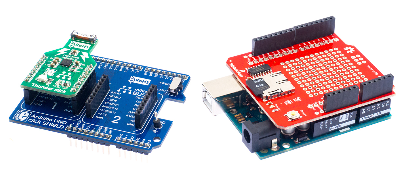
In this project, I will show you how to build a datalogger for lightning events using the AS3935 sensor and one Arduino Uno. The project uses one Thunder click board from MikroElektronika placed on an Arduino UNO click shield and one microSD shield from Sparkfun.
We start from the Arduino Uno, which is a 5V board. The Thunder click comes from the factory set for 3.3V operation, so I have to move the 0Ohm jumper to the 5V position and then place it in socket #1 of the Arduino Uno click shield. The second socket remains empty.
I know there is a microSD click board adapter, but that click board runs only on 3.3V. As such, I had to find another way to add a microSD card to my system; the microSD shield from Sparkfun is just what I needed, as it has the logic level translators needed to use the SD cards in a 5V system.

All parts stacked together, and we are ready to write the software:

AS3935 and SD card: some SPI considerations
The key element in this project is implementing the communication between the Arduino Uno and the AS3935 sensor on one side, and the communication between the Arduino Uno and the SD card on the other side.
As we know from the AS3935 datasheet, this sensor uses SPI mode 1. microSD card uses SPI mode 0. Fortunately, the latest version of Arduino IDE allows us to change SPI modes on the fly, and we can mix devices with different SPI modes on the same bus. This is done by using the SPISettings function:
SPISettings mySettting(speedMaximum, dataOrder, dataMode)
The SPISettings can be passed to the SPI.beginTransaction function to configure the communication:
SPI.beginTransaction(SPISettings(1000000, MSBFIRST, SPI_MODE1));
The current AS3935 libraries are setting the SPI mode at the beginning of the code and don't allow us to change SPI mode on the fly. As such I have decided to take another approach and write myself all the code, without using any of the existing AS3935 libraries.
To communicate with the sensor I wrote two functions, one to write data to the AS3935 registers, and one function to read AS3935 registers. Those functions are as follows:
/*******************************************************************************
* Function Thunder_Write(unsigned short address, unsigned short data1)
* ------------------------------------------------------------------------------
* Overview: Function writes desired byte into specified register address
* Input: register address, byte
* Output: Nothing
*******************************************************************************/
unsigned short Thunder_Write(unsigned short reg_address, unsigned short reg_value)  {
  reg_address = reg_address & 0x3F; // mask bits 6 and 7 (write)
  SPI.beginTransaction(SPISettings(1000000, MSBFIRST, SPI_MODE1));
  digitalWrite(Thunder_CS, 0);
  SPI.transfer(reg_address);
  SPI.transfer(reg_value);
  digitalWrite(Thunder_CS, 1);
  SPI.endTransaction();
}
In AS3935 the first byte sent on the SPI bus combines the destination address and the read/write instruction: bits [7:6] are set to [0,0] for a write cycle, and are set to [0,1] for a read cycle. The register where we write/read is on bits [5:0].
So, to write to an AS3935 register we first clear bits [7:6]. We then begin an SPI transaction, with the required settings for AS3935 (in this code example we set SPI speed to 1MHz, MSB first, SPI Mode 1). We then bring the Thunder_CS lien low to access our sensor.
The SPI transaction consists in sending the address for the destination register, followed by the data to be written. After this, we bring the Thunder_CS line high and we end the SPI transaction by executing SPI,endTransaction();
Reading from an AS3935 register goes in a similar way, but here we set bits [7,6] to [0,1] to indicate that a read cycle follows:
/*******************************************************************************
* Function Thunder_Read(unsigned short address)
* ------------------------------------------------------------------------------
* Overview: Function reads byte from specified address
* Input: register address
* Output: desired byte
*******************************************************************************/
unsigned short Thunder_Read(unsigned short reg_address) {
  // Set SPI to work with AS3935
  unsigned short tmp;
  SPI.beginTransaction(SPISettings(1000000, MSBFIRST, SPI_MODE1));
  reg_address = reg_address & 0x3F;   // mask bits 6 and 7
  reg_address = reg_address | 0x40;   // set bit 6 (read cycle)
  digitalWrite(Thunder_CS, 0);
  SPI.transfer(reg_address);
  tmp = SPI.transfer(0);
  digitalWrite(Thunder_CS, 1);
  SPI.endTransaction();
  return tmp;
}
Besides setting different register values, AS3935 allows for two special commands, as described on page 16 of the datasheet: PRESET_DEFAULT resets all the AS3935 values to their factory values. This is achieved by writing 0x96 to register 0x3C. Automatic calibration of the internal RC Oscillators is performed by the CALIB_RCO command, which means writing 0x96to register 0x3D. A short delay of about 2ms should be implemented in software after issuing direct commands.
SD card and SPI modes
One might observe that I change SPI mode only for the AS3935 sensor. This happens because in the latest Arduino IDE (I use version 1.6.9) SPI mode is automatically set to 0 in the SD card library. If you wish, you can take a look into the \Arduino\libraries\SD\src\utility\Sd2Card.cpp, where you will find on line 269:
settings = SPISettings(250000, MSBFIRST, SPI_MODE0);
With the SPI mode being set to 0 in SD library and with my own read/write functions, the AS3935 and teh SD card can coexist on the same SPI bus with no further issues. I mention here also that the microSD shield uses digital pin 8 as CS, so there are no hardware conflicts.
Calibration of AS3935
For reliable detection of lightning events, the AS3935 must be properly calibrated. The LCO frequency must match the resonance frequency of the antenna (500kHz),
To calibrate the We will configure the AS3935 to output the LCO frequency on the INT pin. We will first set the LCO_FDIV bits [7:6] of register 0x03 to [0,0], which divides the LCO frequency by 16. Then we set bit 7 of register 0x08, thus enabling the output of the LCO:16 on INT pin.
The desired LCO frequency is 500kHz ±3.5%, so we expect a frequency of 31250Hz on the INT pin. If we are outside the range [30157:32343] then we are outside the ±3.5% range and the calibration failed.
Changing of the LCO frequency is done by changing the internal Tuning Capacitors (from 0 to 120pF in steps of 8pf), which are controlled via TUN_CAP bits [3:0] of register 0x08. As the calibration process is not linear, we will try all the values, measuring the number of pulses that come over a 100ms period, and keeping the tuning capacitor that gives the closest frequency to 500kHz. We also dump some diagnostic data to the SD card.
I will mention here that in my code the calibration process is performed only once. One should take care that changes in temperature and humidity might impact the LCO frequency, so when running this datalogger for extended periods of time it might be a good idea to repeat calibration from time to time (every hour or such).
AS3935: event detection
Whenever an event is detected the AS3935 sensor pulls the INT pin high. In Arduino Uno, this triggers an interrupt which sets the AS3935_INT_Triggered flag.void AS3935_IRQ()
{
AS3935_INT_Triggered = 1;
}
This flag is checked in the main loop:
if(AS3935_INT_Triggered) {
     current_millis = millis();   // Record timestamp
     AS3935_INT_Triggered = 0;    // Clear interrupt flag
     delay(2); // wait 2ms before reading the event (see datasheet page 22)
     tmp = Thunder_Read(0x03);    // Read event register. This also clears Thunder_INT
     tmp = tmp & 0x0F;            // Mask interrupt bits
          String logString = "";
     logString += String(current_millis);
     logString += ',';
     if (tmp == 0x00){  // Statistics changed
       logString += String("New statistics,0,NaN,NaN");
     }
     if (tmp == 0x01){  // Noise
        logString += String("Noise detected,1,NaN,NaN");
     }
     if (tmp == 0x04){  // Man-made disturber
        logString += String("Disturber detected,2,NaN,NaN");
     }
     if (tmp == 0x08){  // Lightning
        logString += String("Lightning detected,3,");
        // Get distance to the lightning event
        // this means bits [5:0] of register 0x07
        tmp = Thunder_Read(0x07);
        tmp = tmp & 0x3F;         // mask bits 7:6
        logString += String(tmp); // add distance to the string
        logString += String(","); // separator for csv format
        // Get energy of lightning event
        // this means bits [4:0] of register 0x06
        // and content of registers 0x04 and 0x05
        en_tmp = Thunder_Read(0x06);
        en_tmp = en_tmp & 0x3F;         // mask bits 7:6
        L_energy = L_energy | ( en_tmp << 16 );
        en_tmp = Thunder_Read(0x05);
        L_energy = L_energy | ( en_tmp << 8 );
        en_tmp = Thunder_Read(0x04);
        L_energy = L_energy | en_tmp;
        logString += String(L_energy);
     }
     // write data to sd card
     File dataFile3 = SD.open("datalog.csv", FILE_WRITE);
     if (dataFile3) {
      dataFile3.println(logString);
      dataFile3.close();
      // print to the serial port too:
      Serial.println(logString);
    }
  }
Event codes are stored in bits [3:0] of register 0x03. Reading the event code clears also the interrupt and brings the INT line of the AS3935 low. The AS3935_INT_Triggered is cleared in software.
After reading the event code we compare it against the values in table 18 in the datasheet (page 22). If there's lightning we also read the energy to the lightning and the lightning energy. Otherwise, we write to the SD card only the timestamp and the event name and code.
AS3935: lightning datalogger code
The whole Arduino code for the datalogger is:
A few explanations regarding the code
The datalogger creates two files on the SD card: messages.txt contains some debug transformation such as register dumps and calibration info, while datalog.csv stores events. Four types of events are recorded:
- When clearing statistics (most likely at startup) a "New statistic event" is issued.
- Noise events
- Disturbers (man-made perturbations)
- Lightnings. In this case we also store the distance to the lightning event and the lightning energy


0 Comments